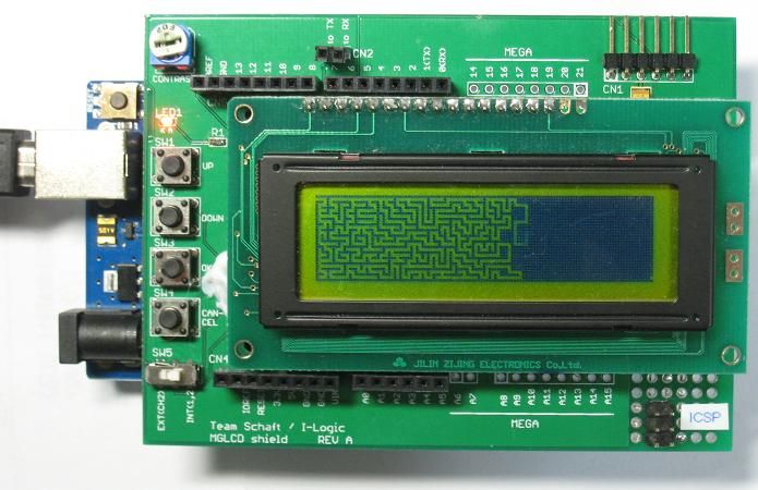
122x32 monochrome graphic LCD shield (Rev. A)
This page was originally written in Japanese by Synapse and translated into English by Synapse.
A Japanese web shop named aitendo sells an inexpensive graphic LCD, S12232ZA, which costs only 350 yen. It requires, however, as many as 12 signal lines, so it uses up more than half of Arduino Uno's I/O pins.
Thus I decided to design a LCD shield that requires only 2 signal lines (RX and TX) by employing a microcontroller that communicates with Arduino via a serial interface and that also controls a graphic LCD. A library for LCD control named MGLCD makes it easy to display graphical objects on a screen.
With this shield, you can save signal lines of Arduino, in addition to saving time for prototyping. Besides, you can save space in flash memory because the code for LCD control is in the microcontroller on this shield, not on Arduino.
Figure 1 shows the block diagram of the 122x32 monochrome graphic LCD shield (heareafter graphic LCD shield).
A 122x32-pixel monochrome graphic LCD, S12232ZA is employed. This LCD has no backlight.
ATmaga328P, which is also used in Arduino Uno, is employed as a microcontroller for LCD control. This microcontroller parses the commands sent form Arduino via a serial interface. And then it controls a LCD according to the commands. In this way, you can display graphical objects using only two signal lines: RX and TX.
16MHz crystal oscillator is used as a clock source for ATmega328P. So ATmega328P operates at the same clock frequency as Arduino Uno.
Other than a LCD, one LED and four push-button switches are also connected to ATmega328P. You can control these LED and switches via a serial interface, not using extra I/O pins of Arduino.
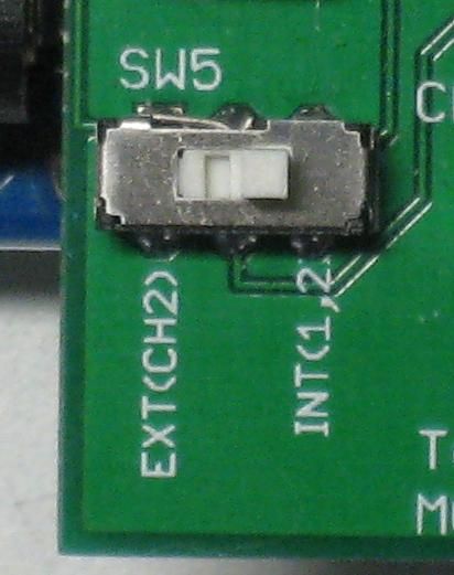
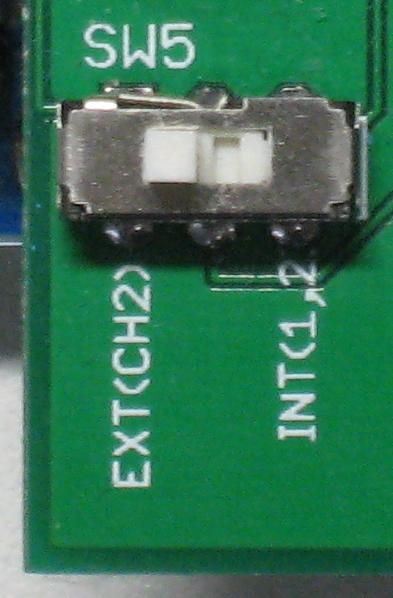
When you use hardware serial on Arduino, pins for serial communication are fixed: pin 0 for RX and pin 1 for TX. In this case, you may slide SW5 on the graphic LCD shield toward INT side. Then TX and RX pins of ATmega328P are internally connected to pin 0 and pin 1 of Arduino, respectively.
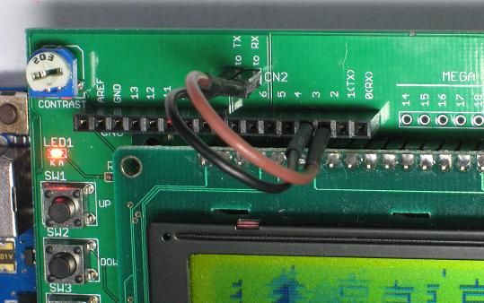
When you use software serial on Arduino, you can assign serial signals to any 2 pins that are supported by software serial. In this case, you may slide SW5 on the shield toward EXT side. TX and RX pins of ATmega328P are connected CN2, and you have to connect them to Arduino manually with jumper wires. The photograph shown below illustrates how to connect TX and RX pins of ATmega328P to pin 2 and pin 3 of Arduino respectively.
Although this shield supports only Arduino Uno and Arduino MEGA 2560 so far, it can be connected to 3.3V-I/O microcontrollers such as Arduino Due and GR-SAKURA if a level converter is added. Besides, it can be connected to a PC with the assistance of an external USB-serial converter. I plan to develop support software for various microcontrollers and PCs.
The bootloader for Arduino Uno (optiboot) is burned onto the ATmega328P on this shield. So you can easily update its firmware using Arduino IDE and a USB-serial converter.
To begin with, I will show you how to use the graphic LCD shield. I will show you detailed information such as a circuit schematic and a software library later.
As you can see in the photographs below, there are pin headers to connect this shield to Arduino on the bottom side of the shield, and there are sockets at the same locations on the top side.
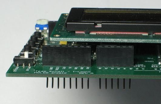
Most of the pins in the headers on the bottom side are only connected to the corresponding pins in the sockets on the top side. If you slide SW5 toward INT side, however, pin 0 and pin 1 are connected to the microcontroller in the shield, and the shield functions as a serial LCD module.
By the way, I wanted to print "INT(0,1)" to indicate that pin 0 and pin 1 are connected internally to the serial-interface pins of the microcontroller. But somehow I mistook it for "INT(1,2)." Furthermore I found other several mistakes, and I ended up revising the PCB. Maybe I was a little tense when designing the PCB. I will write more about the revision later...
If you merely want to display characters on a LCD screen, you can use this shield as a 20x4 serial terminal without using any special libraries. (I describe how to display graphic objects later.)
The following is an example sketch that displays numbers from 1 to 10 at intervals of 1 second.
void setup()
{
  Serial.begin(1200);
  delay(5000);
  for(int i=1; i<=10; i++) {
    Serial.println(i);
    delay(1000);
  }
}

void loop()
{
}
As you can see in the above example, there is no difference between this sketch and a sketch that sends numbers via a serial interface at 1200 bps. If you don't use a special library designed for this shield, it functions as a serial terminal that operates at 1200 bps. Its communication speed is fixed at a slow rate (1200 bps) in order to avoid skipping characters because no flow control is used.
Burn the sketch onto Arduino after sliding SW5 toward EXT side. After you finish to burn the sketch, slide SW5 toward INT side within 5 seconds (during delay(5000) is executed). Since Arduino uses pin 0 and pin 1 during you burn a sketch onto it, you have to detach these pins from Arduino during that time. This is the reason why you have to keep SW5 toward EXT side during you burn a sketch.
The following video explains the process when you burn the sample sketch and display numbers form 1 to 10 on a LCD display.
If you want to use pin 0 and pin 1 of Arduino for other purposes, you can control LCD with other pins using software serial library. The following example shows how to use pin 2 for RX and pin 3 for TX. (This example is for Arduino Uno. As for Arduino Mega 2560, pin 2 cannot be used as RX pin, so use a pin that is supported by software serial, such as pin 10.)
#include <SoftwareSerial.h>
SoftwareSerial mySerial(2, 3); // RX:pin 2 TX:pin 3
void setup()
{
  mySerial.begin(1200);
  //delay(5000);
  for(int i=1; i<=10; i++) {
    mySerial.println(i);
    delay(1000);
  }
}

void loop()
{
}
Slide SW5 toward EXT side before burning this sketch. Then signal lines in Arduino and graphic LCD shield are detached.
By the way, I initially intended to print "EXT(CN2)" to show that CN2 have to be fed with signals externally, somehow I actually printed "CH2."
You have to connect CN2 to Arduino's serial signal lines with jumper wires. In this case, pins for RX and TX are designated in the sketch as pin 2 and pin 3, respectively, so you should connect the pin labeled as "to RX" to pin 2 of Arduino, and you should connect the pin labeled as "to TX" to pin 3 of Arduino.
Now you can burn the sketch onto Arduino. LCD starts to display numbers after you burn the sketch. In this case, pin 0 and pin 1, which are used to burn the sketch, are not used for other purpose, so you don't have to slide SW5 each time you burn a sketch. Thus delay(5000), which is written in the next line of mySerial.begin(1200) in order to pause 5 seconds necessary for you to slide SW5, is invalidated.
If you want to use other pins with software serial library, modify the following line in your sketch. You have to change the connection between CN2 and Arduino according to the modification of your sketch.
SoftwareSerial mySerial(2, 3); // RX:pin 2 TX:pin 3
Even though the LCD has only 4 lines, it is very useful to be able to show messages at a location very close to Arduino. As you know, Arduino IDE has no debug functions such as break points or execution traces, so we often use what is called "printf debug." It is sometimes painful to see alternately Arduino and a screen of terminal software such as HyperTerminal. In such a case, you can see debug information on a LCD screen close to Arduino if you use this shield.
In addition, if you want to make your gadget portable, its screen must be small and low power consumption. This shield will be one of the best answers.
As a simple example of graphic LCD's application, I describe how to display values obtained by Arduino's analogRead function. A voltage divider that consists of a potentiometer is used as a voltage source for an ADC.
Voltages ranging from 0V to 5V obtained by a voltage divider that divides 5V supply are applied to A0 pin. As illustrated in Figure 2, connect pin 1 of a potentiometer to GND, pin 2 to the A0 pin, and pin 3 to 5V. I used 10k-ohm potentiometer, but 5k-, 20k-, and 50k-ohm potentiometers will work, too.
This time, I used a trimmer potentiometer, which is shown blow, because it is easy to place both a graphic LCD shield and a trimmer potentiometer in the same frame when I took a photograph. However, a trimmer potentiometer requires cutting universal PCB and soldering when you mount it to Arduino. So, if you do this examination by your self, a potentiometer with a knob is preferable to a trimmer potentiometer.
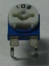
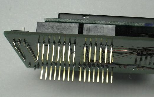
Pins of a trimmer potentiometer cannot be inserted into the socket of a graphic LCD shield, so I processed it into the form shown below.
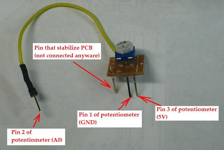
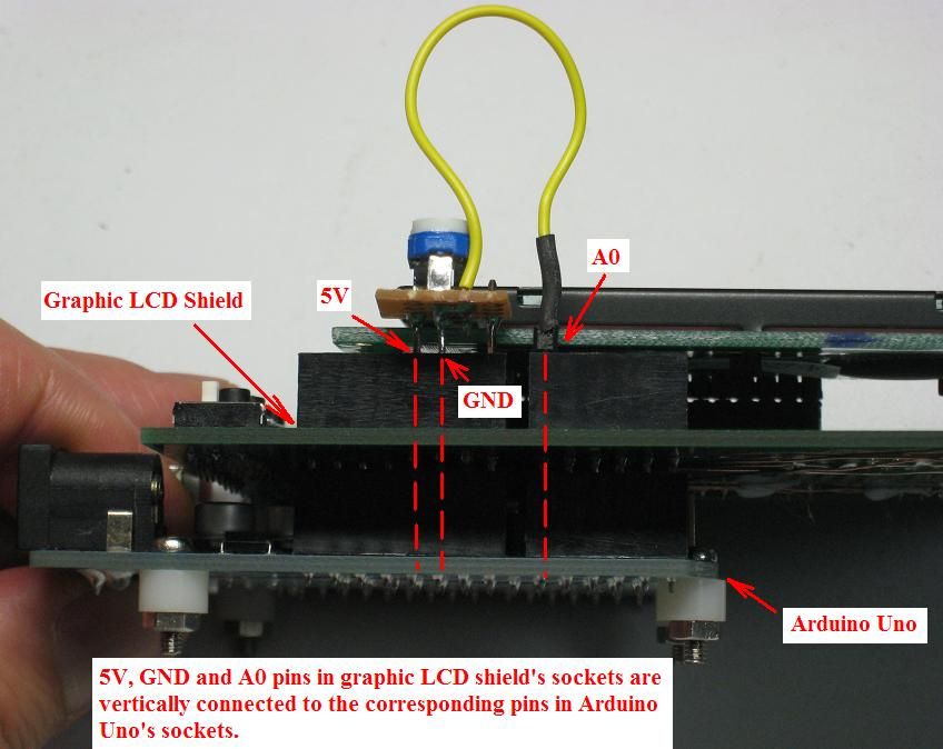
3 pins of this trimmer potentiometer are inserted to the socket of a graphic LCD shield so that they are connected to 5V, GND and A0 pin.
With this connection, if the trimmer is turned fully counterclockwise, 0V is applied to the A0 pin, and if the trimmer is turned fully clockwise, 5V is applied to the A0 pin. Since the ADCs in Arduino Uno have 10-bit resolution, if the trimmer is turned fully counterclockwise, the output is 0, and if the trimmer is turned fully clockwise, the output is 1023. Let's confirm it by an experiment.
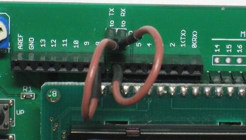
This time, I chose pin 7 as RX signal, and pin 8 as TX signal when initializing software serial. So, jumper wires are connected as the photograph shown below. (This example is for Arduino Uno. As for Arduino Mega 2560, pin 7 cannot be used as RX pin, so use a pin that is supported by software serial, such as pin 10.)
The following sketch is burned onto Arduino Uno after SW5 has been slid toward EXT side.
#include <SoftwareSerial.h>

SoftwareSerial mySerial(7,8); // RX:pin 7 TX:pin 8

void setup()
{
  // initialize software serial
  mySerial.begin(1200);
}

void loop()
{
  // obtain a result of an A/D conversion
  int val=analogRead(A0);

  // display a bar graph
  for(int i=0; i<=15; i++) {
    if(i<(val*15+512)/1024) {
      mySerial.print('*');
    } else {
      mySerial.print(' ');
    }
  }

  // display the result of A/D conversion
  mySerial.println(analogRead(A0));
}
Then the results of A/D conversions are displayed in the form of simple bar graphs and numbers as show in the following video.
In the next page, a library that can display graphic objects is introduced.
| return to the top page | proceed to the next page |