This page was originally written in Japanese by Synapse and translated into English by Xuchun Fang.
Previously, I explained the terminal mode where the graphic LCD shield is used as 1200bps serial terminal. It has the advantage of being able to display characters in the same way as in communication between PC terminals. On the other hand, the disadvantage is that the functions of the graphic LCD shield is not fully utilized. This time, I will explain the MGLCD mode, by which the performance of the graphic LCD shield can be fully utilized.
MGLCD (Monochrome Graphic Liquid crystal Display) is a library name for Arduino, used for controlling monochrome LCD. The library can also be used in the case where LCD is directly connected to Arduino without using graphic LCD shield. As of May 2013, SG12232C, SG12864ASLB-GB and S12232ZA were supported. The newest MGLCD version was Ver. 0.23 when this document was written. Download it from the following link. Also, the operation testing of the library was carried out in Windows version of Arduino IDE 1.0.1 and 1.0.4.
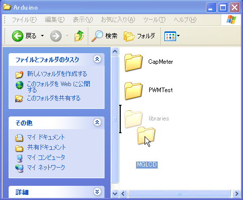
By clicking the above link, you can download a zip file. Unzip it and you will see a folder named MGLCD. Please move or copy that folder as a whole to My Document\Arduino\libraries. If there is no such library folder in My Document\Arduino, create that folder, then move/copy MGLCD folder. The install process is finished.
Here, let’s see how to draw a diagonal line on LCD screen by using the installed MGLCD library.
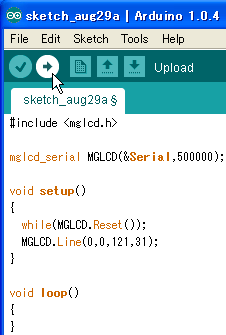
Input the following sketch in Arduino IDE.
#include <mglcd.h>
mglcd_serial MGLCD(&Serial,500000);

void setup()
{
  while(MGLCD.Reset());
  MGLCD.Line(0,0,121,31);
}

void loop()
{
}
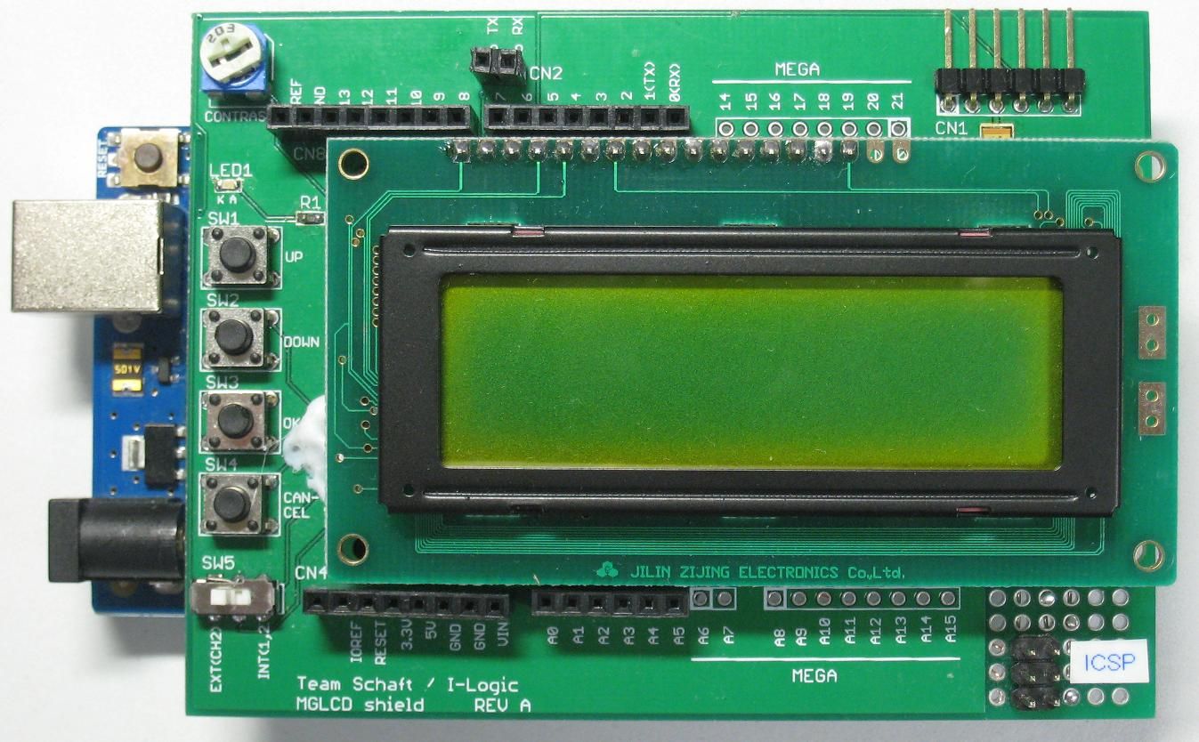
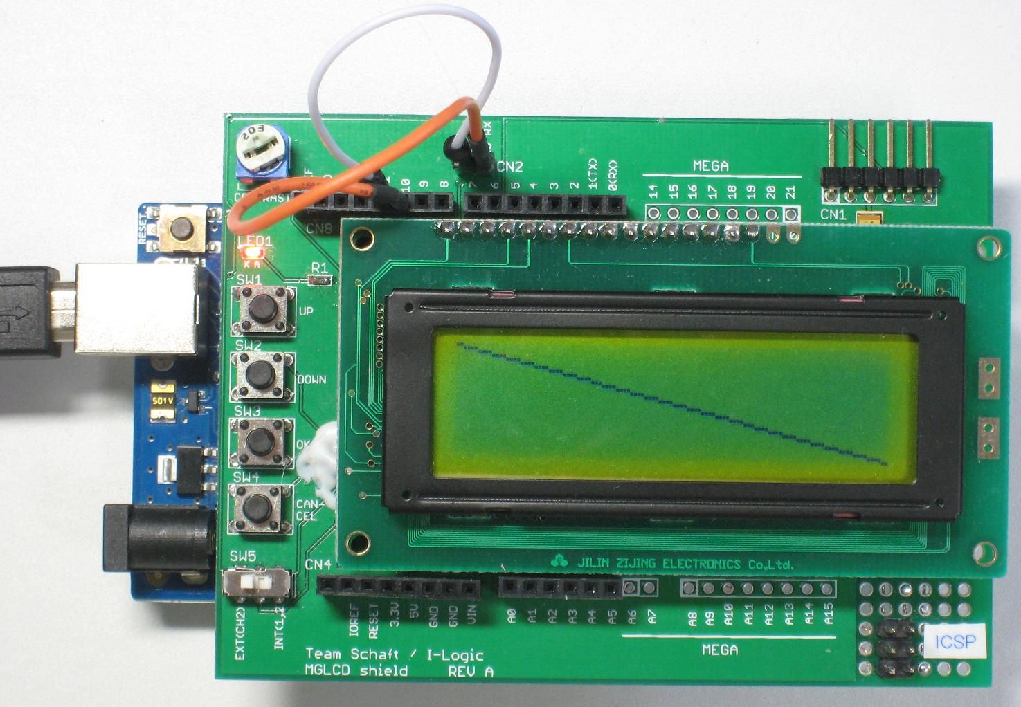
Next, Install the graphic LCD shield onto Arduino and switch SW5 to the EXT side.
Connect USB cable to Arduino, and write the sketch to Arduino.
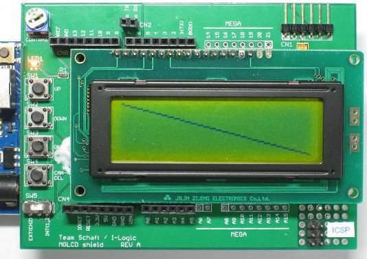
Now, when you switch SW5 to INT side, a diagonal line will be drawn from up-left to bottom-right in the screen.
Let me explain the sketch in more detail.
The first line,
#include <mglcd.h>
is a declaration for importing MGLCD library's header file. Note that in order to use MGLCD library, it's necessary to include this line in the beginning of the sketch.
The second line,
mglcd_serial MGLCD(&Serial,500000);
is also a statement for using MGLCD library. In order to use MGLCD library, it’s necessary to declare an object variable of mglcd_serial type. In the above line, MGLCD is the name of that variable. After the declaration, the functions in the MGLCD library are called in the form of MGLCD.function_name(argument, ...).
However, it’s not necessarily to use a variable name as MGLCD. For example, as in
mglcd_serial foo(&Serial,500000);
using variable name foo is also ok. But in that case, it’s necessary to use foo.function_name(argument, ...) for calling functions in the MGLCD library.
&Serial means using hardware serial to communicate with graphic LCD shield. In the case of Arduino Uno, &Serial is a must. By this way, pin 0 (RX) and pin 1 (TX) of Arduino Uno are used to communicate with graphic LCD shield.
In the case of Arduino Mega 2560, there are 4 hardware serial ports in total. They are named Serial (RX: pin 0, TX: pin 1), Serial1 (RX: pin 19, TX: pin 18), Serial2 (RX: pin 17, TX: pin 16), Serial3 (RX: pin 15, TX: pin 14) respectively. For example, in order to use pin 15 and pin 14 for communication with graphic LCD shield, instead of pin 0 and pin 1, it’s ok to use
mglcd_serial MGLCD(&Serial3,500000);
In that case, it’s necessary to connect jump wires and operate SW5. This will be described in detail later.
The number 500000 indicates speed when communicating (unit: bps). That means, using 500000bps (500kbps) in communicating. By changing this number, you can use a slower speed to communicate. The communication speeds which can be used are 300bps, 600bps, 1200bps, 2400bps, 4800bps, 9600bps, 14400bps, 19200bps, 28800bps, 38400bps, 57600bps, 115200bps, 250000bps and 500000bps. For example, for communicating in 9600bps, use
mglcd_serial foo(&Serial,9600);
In setup function, line
while(MGLCD.Reset());
is necessary for initializing graphic LCD shield. In a sketch using MGLCD library, it's necessary to call Reset function to initialize graphic LCD shield at first. However, if using
MGLCD.Reset();
alone to call Reset function, initialization may be failed. The reason is that when calling Reset function, the micro-controller in the graphic LCD shield may not yet finish starting, or the RX pin and TX pin wires may not be ready because SW5 operation has not completed. When initialization succeeds, Reset function will return 0, and when it fails, a negative value is returned. Therefore by using
while(MGLCD.Reset());
initialization will be repeated until it succeeds.
Next,
MGLCD.Line(0,0,121,31);
calls Line function to draw a line. In this case, a line is drawn from coordinate (0, 0) (upper-left of the screen) to coordinate (121, 31) (bottom-right of the screen). That is, draw a diagonal line in the screen.
The sketch runs as described above.
If you want to use software serial to communicate when hardware serial ports are not enough, change the above sketch as follows.
#include <mglcd.h>
#include <SoftwareSerial.h>
SoftwareSerial mySerial(10,11);
mglcd_SoftwareSerial MGLCD(&mySerial,38400);

void setup()
{
  while(MGLCD.Reset());
  MGLCD.Line(0,0,121,31);
}

void loop()
{
}
In the case of using software serial, it’s necessary to declare
#include <SoftwareSerial.h>
and include a header file named SoftwareSerial.h. In addition, it's necessary to use
SoftwareSerial mySerial(10,11);
to declare a variable of SoftwareSerial type. In the above example, the variable is named mySerial though, other variable name is also ok. For example, if the variable is named foo1, the line becomes
SoftwareSerial foo1(10,11);
However, it becomes necessary to change the next line to
mglcd_SoftwareSerial MGLCD(&foo1,38400);
for matching. The two numbers (10 and 11) in the declaration
SoftwareSerial mySerial(10,11);
indicate Arduino pin numbers used in communication with the graphic LCD shield. In this case, pin 10 is used for RX, pin 11 is used for TX.
To use other pins for communication, it's ok by changing these numbers. However, note that in the case of Arduino MEGA 2560, all pins could not be used as RX pin. For details, refer to explanation page for software serial library.
mglcd_SoftwareSerial MGLCD(&mySerial,38400);
declares a variable MGLCD of type mglcd_SoftwareSerial for using MGLCD in communication via software serial. After this declaration, the MGLCD library functions are called in the form of MGLCD.function_name(argument, ...). Though MGLCD is used as the variable name in this example, if declared as
mglcd_SoftwareSerial foo2(&mySerial,38400);
the variable name becomes foo2. In this case, the MGLCD library functions are called in the form of foo2.function_name(argument, ...).
The two arguments &mySerial and 38400 indicate pointer to the SoftwareSerial type variable and communication speed (bps) respectively. In the case of using software serial, the communication speeds which can be used are 300bps, 600bps, 1200bps, 2400bps, 4800bps, 9600bps, 14400bps, 19200bps, 28800bps and 38400bps. By
MGLCD.Line(0,0,121,31);
a line is drawn from coordinate (0, 0) to coordinate (121, 31).
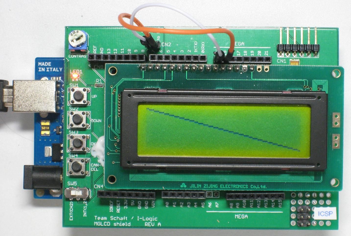
For running the sketch, connect CN2's “to RX” to pin 10, “to TX” to pin 11 respectively using jump wires, and switch SW5 to EXT side. After that, the sketch will be written to Arduino, and a diagonal line will be drawn from upper-left to bottom-right of the screen.
As described above, there are 4 serial ports in Arduino Mega 2560. Besides Serial, Serial1, Serial2 and Serial3 can also be used. For example, for communicating with graphic LCD shield by using Serial3, the sketch will be as follows.
#include <mglcd.h>

mglcd_serial MGLCD(&Serial3,500000);

void setup()
{
  while(MGLCD.Reset());
  MGLCD.Line(0,0,121,31);
}

void loop()
{
}
In the above sketch, only the following line is different from the sketch using Serial to communicate.
mglcd_serial MGLCD(&Serial3,500000);
Of course, for using Serial1 or Serial2, you only need to change &Serial3 to &Serial1 or &Serial2.
To run the sketch, switch SW5 to EXT side, and connect CN2's “to RX” to pin 15, “to TX” to pin 14 respectively using jump wires, then write the sketch. Having done that, a diagonal line will be drawn.
In the previous page, A/D conversion results are displayed in text. This time, let's see how to display them in graphic.
As described in figure 2 in the previous page, attach the variable resistor to the graphic LCD shield and switch SW5 to the EXT side, then write the following sketch to Arduino.
#include <mglcd.h>

mglcd_serial MGLCD(&Serial,500000);

void setup()
{
  // initialize the graphic LCD shield
  while(MGLCD.Reset());
}

void loop()
{
  // acquire A/D conversion value (0~1023)
  int val=analogRead(A0);

  // display A/D conversion value
  MGLCD.Locate(0,0);
  MGLCD.print(val);
  MGLCD.ClearRestOfLine();

  // display bar graph
  val/=8;
  if(val>=MGLCD.GetWidth()) val=MGLCD.GetWidth()-1;
  MGLCD.FillRect(0,9,val,MGLCD.GetHeight()-1,1);
  MGLCD.FillRect(val+1,9,MGLCD.GetWidth()-1,MGLCD.GetHeight()-1,0);

  delay(200);
}
After the sketch is written, switch SW5 to INT side. And the A/D conversion value is displayed in number and bar graph.
The above operations are put together in the following video.
Let me explain the sketch in brief.
int val=analogRead(A0);
is used to get the A/D conversion value.
MGLCD.Locate(0,0);
MGLCD.print(val);
MGLCD.ClearRestOfLine();
are used to display the A/D conversion value in number in the upper-left of the screen.
Locate function is for indicating display position of characters. By calling Locate(0,0), the characters will be subsequently displayed on the upper-left of the screen.
The usage of the print function is the same as Serial.print.
ClearRestOfLine function is for clearing characters from the present display position to the end of line.
val/=8;
if(val>=MGLCD.GetWidth()) val=MGLCD.GetWidth()-1;
MGLCD.FillRect(0,9,val,MGLCD.GetHeight()-1,1);
MGLCD.FillRect(val+1,9,MGLCD.GetWidth()-1,MGLCD.GetHeight()-1,0);
are used to display the A/D conversion value in bar graph.
val/=8;
is for calculating bar graph length by dividing the A/D conversion value with 8. This is based on that in regard to the maximum A/D conversion value of 1023, the number of pixels in horizontal direction of the LCD, which is 122, is approximately 1/8 of the former.
if(val>=MGLCD.GetWidth()) val=MGLCD.GetWidth()-1;
is used to adjust the length of the bar graph, if the A/D conversion value is too big. 1023 divided by 8 get 127 (the digits below decimal point are dropped). Because this value is bigger than the number of pixels in horizontal direction of the LCD (122 pixels), 121 is used for the upper limit (the number of pixels in horizontal direction - 1). GetWidth function returns the number of pixels in horizontal direction (122).
MGLCD.FillRect(0,9,val,MGLCD.GetHeight()-1,1);
is used to draw the bar graph. FillRect function draws a filled-in rectangle. It's format is as follows.
FillRect(x coordinate1, y coordinate1, x coordinate2, y coordinate2, color)
By calling this, a specified color is filled in the rectangle formed with (x coordinate1, y coordinate1) and (x coordinate2, y coordinate2) as diagonal. The color is white with 0, black with 1.
GetHeight function returns the number of pixels in vertical direction of the screen(32).
MGLCD.FillRect(val+1,9,MGLCD.GetWidth()-1,MGLCD.GetHeight()-1,0);
is used to fill the space to the right of the bar graph with white.
In the next page, the functions related to text display which can be used though MGLCD library are explained.
| back to the previous page | return to the top page | proceed to the next page |